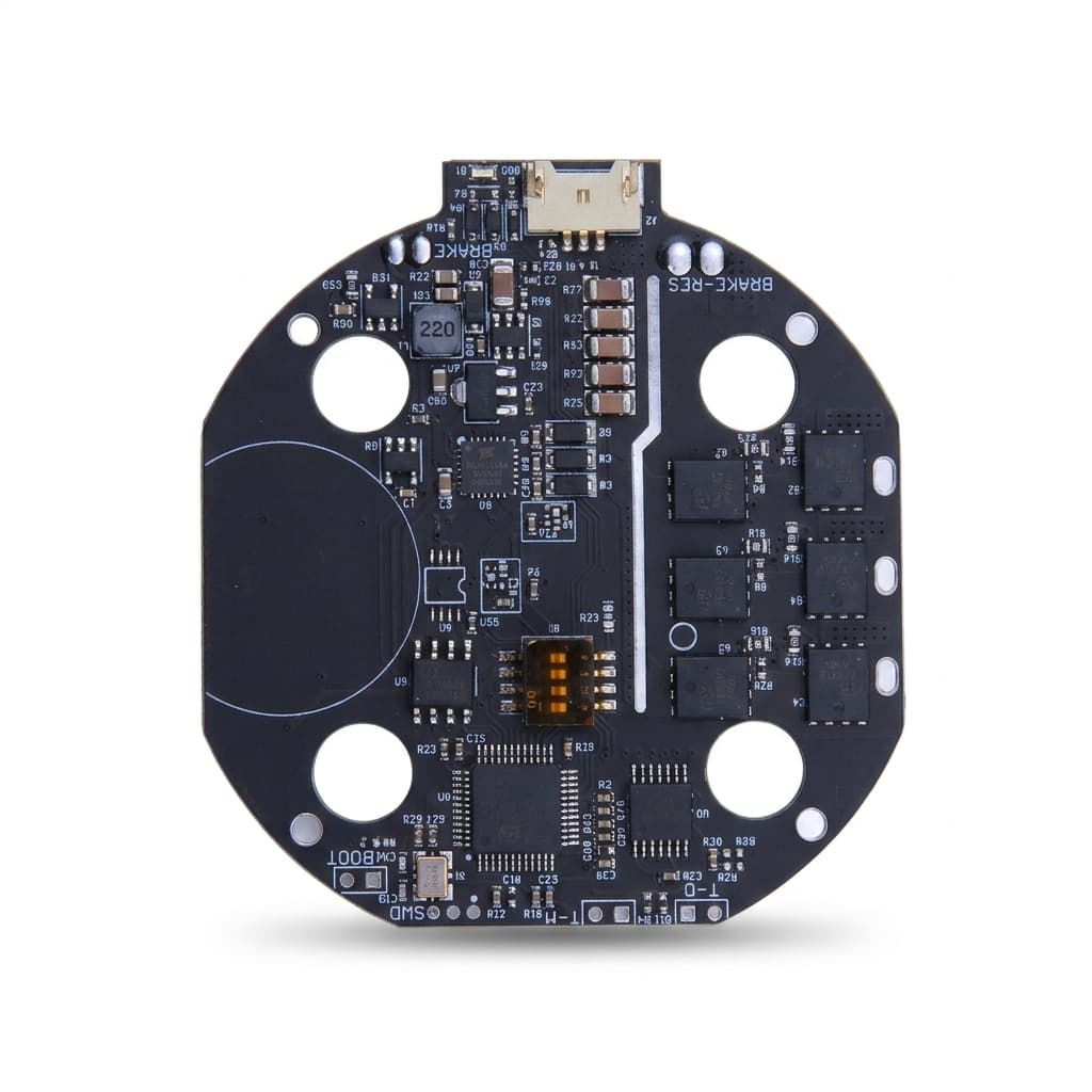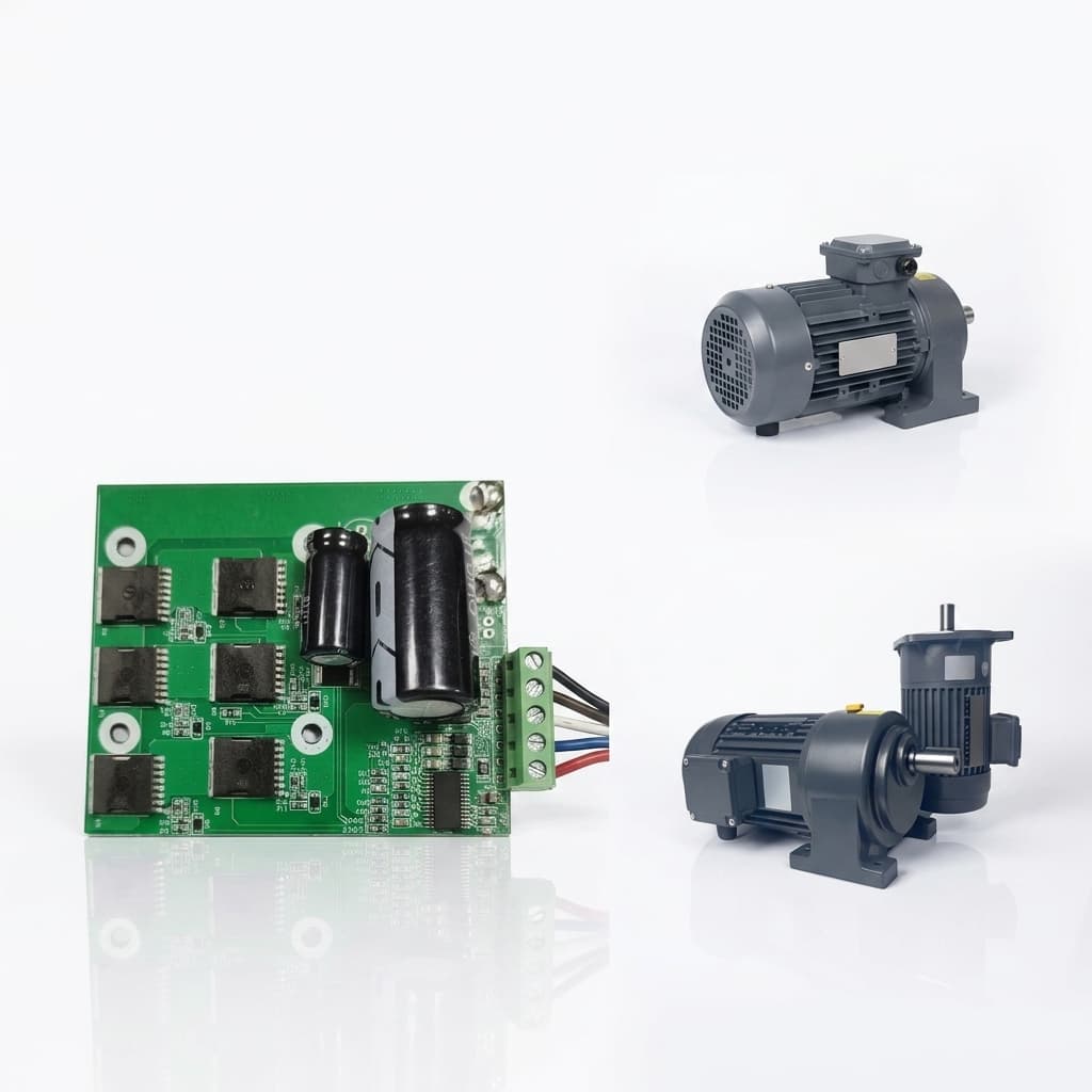
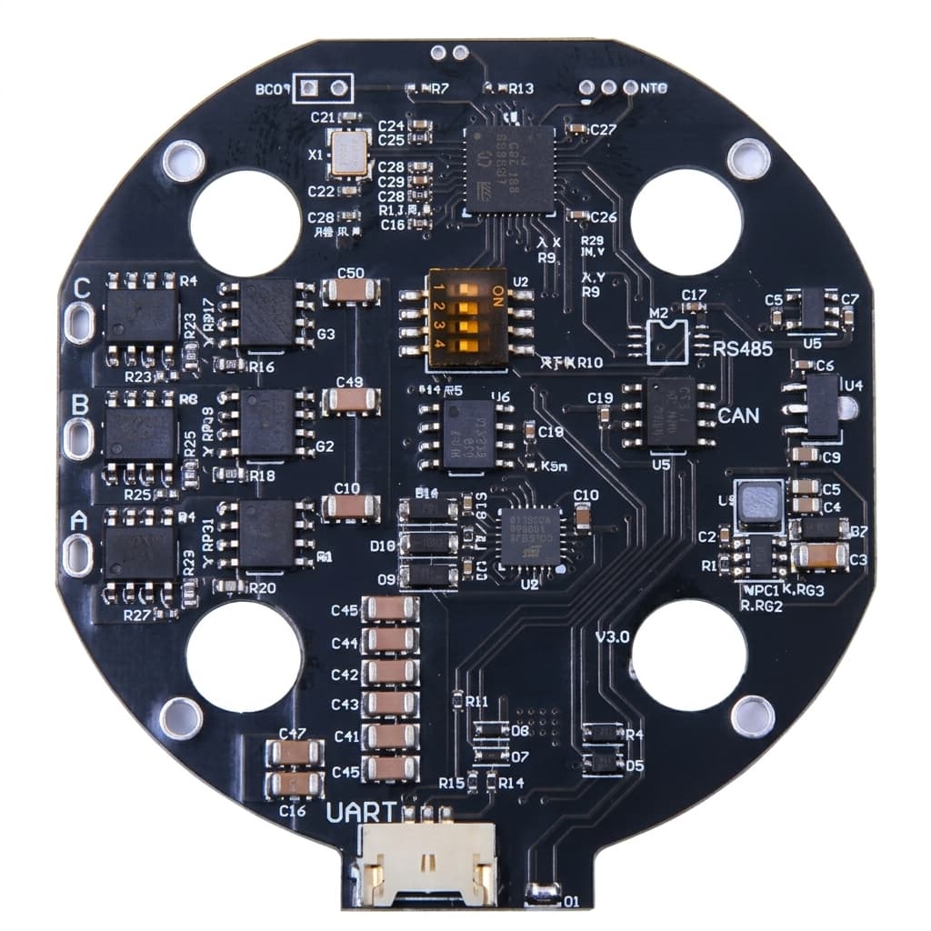
Servo PCBA and SMT

OEM support for servo drive PCB assembly, SMT production, test fixtures, conformal coating, and electronics manufacturing documentation.

Best Fit For:For robotics teams that need electronics manufacturing support for custom servo drives and smart servo modules.
Servo drive PCBA and SMT manufacturing

Capability Highlights

  • Prototype PCBA and batch SMT coordination
  • Power stage, encoder, connector, and thermal layout review
  • AOI, ICT, FCT, burn-in, and serialized test planning

Typical Engagement Scope

  • Micro servo drive boards
  • Embedded joint controller PCBA
  • Smart servo electronics
  • Multi-axis robot control boards

Execution Focus

  • BOM sourcing and alternates
  • DFM for SMT, connectors, heat sinks, and test points
  • Functional test firmware and fixture design

Program Evaluation Matrix

Program MetricTypical RangeProcurement Value
Test coverageAOI, ICT, FCT, burn-in by projectServo drive failures are expensive once boards are sealed inside robot joints.
Power-stage marginMOSFET/GaN rating, current sensing, copper, heat pathCompact servo boards fail when electrical, thermal, and enclosure constraints are treated separately.
TraceabilityBOM revision, firmware version, serial number, fixture logTraceable electronics records make pilot issues easier to isolate before batch shipment.

Program Control Logic

SituationRecommended PathEvidence to Confirm
The servo drive board must fit inside a compact jointReserve test points, heat-spreading copper, connector clearance, isolation spacing, and fixture access before PCB freezePCB outline, keep-outs, layer stack, copper weight, test access, connector height, and enclosure section
Prototype boards need to become repeatable SMT productionPlan AOI, ICT, FCT, firmware flashing, calibration, burn-in, and serial records as production deliverablesGerbers, BOM, pick-and-place, firmware image, fixture spec, panelization plan, and inspection limits
Power-stage heat or component alternates may change behaviorControl MOSFET/GaN, current sensors, gate drivers, MCUs, connectors, and feedback components under ECOApproved AVL, alternate list, thermal sample data, load-cycle data, and buyer approval for substitutions

RFQ Preparation Checklist

  1. Gerbers, BOM, pick-and-place, firmware, and test plan
  2. Voltage/current target, heat path, connector load, and coating need
  3. Prototype quantity, panelization constraints, and inspection records
  4. ICT/FCT coverage, flashing method, calibration data, and serial traceability
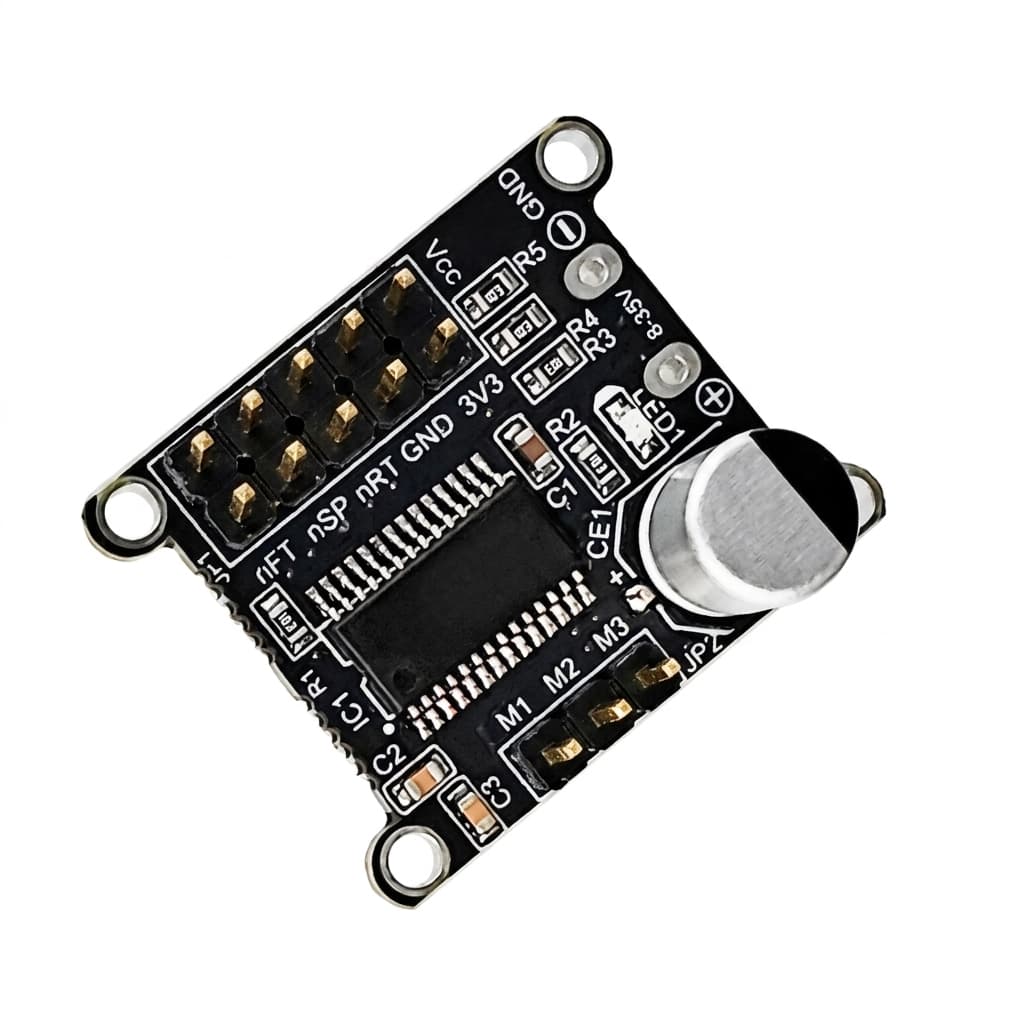
Risk and Mitigation

  • No production test points on compact PCBA: Reserve test access and fixture strategy before PCB layout is frozen.
  • BOM alternates change motor-control behavior: Approve alternates for current sensors, gate drivers, MCUs, connectors, and feedback interface components under ECO control.

Program QA Flow

CheckpointMethodPass Evidence
DFM and test access reviewCheck panelization, component placement, thermal copper, isolation, connector load, and ICT/FCT accessPCB DFM report and accepted fixture access points before layout freeze
SMT production validationRun AOI, ICT/FCT, firmware flashing, calibration, burn-in sampling, and first-article inspectionSerialized PCBA report, approved BOM revision, firmware version, and fixture result
BOM alternate controlApprove alternates for current sensors, gate drivers, MCUs, connectors, feedback parts, and power devicesAVL, ECO record, buyer approval, and retest data for behavior-sensitive substitutions

Program Evidence

Engineering Evidence Pack for Servo PCBA and SMT

For OEM pages, the first engineering review defines execution gates, missing data, and production-readiness evidence before kickoff.

Scope baseline

Motor, drive, actuator, firmware, harness, fixture, and test responsibility are separated before quotation.

Missing-input list

Open items such as torque-speed data, duty cycle, envelope, protocol, encoder, and target launch country are flagged early.

Sample validation plan

Prototype checks are tied to load profile, thermal rise, backlash, noise, current limit, and end-of-line pass criteria.

Quote assumptions

Tooling, fixture, pilot lot, annual forecast, packaging, documentation, and delivery assumptions are made explicit.

Evidence GroupWhat to AttachBuyer Value
Motion and thermalTorque-speed target, current limit, duty cycle, temperature path, and derating assumption.Separates continuous-duty capability from peak torque claims before sample approval.
Interface controlSTEP or drawing revision, flange, bore, cable exit, connector, encoder, and protocol map.Keeps motor, drive, harness, and firmware assumptions aligned before tooling.
Validation recordEVT, DVT, PVT gate criteria, EOL checklist, burn-in profile, and serial or lot traceability.Gives engineering and procurement a common pass/fail basis for pilot lots.
Commercial pathPrototype quantity, pilot build target, annual forecast, delivery country, and packing notes.Improves quote precision and avoids late shipping or documentation surprises.

Related Products

Servo OEM PCBA layout design
Servo OEM SMT manufacturing line
Servo OEM AOI and ICT inspection

Buyer FAQ

Can you produce irregular servo drive PCBs?

Yes. Irregular outlines and stacked boards can be reviewed with manufacturing and test constraints included.

Can firmware loading and fixture tests be included?

Yes. Firmware flashing, calibration routines, ICT/FCT fixtures, burn-in, and serialized reports can be scoped by project.

Related Resources

Inquiry Email

[email protected]

Include drawings, torque/speed, protocol, and prototype quantity.

Instant Chat

+8618857971991

Direct response from our engineering team.